Power Triangle
While direct current has one form of power, alternating current has three different forms of power that are related in a unique relationship. In this chapter, you will learn that power in AC circuits cannot be calculated in the same manner as in DC circuits.
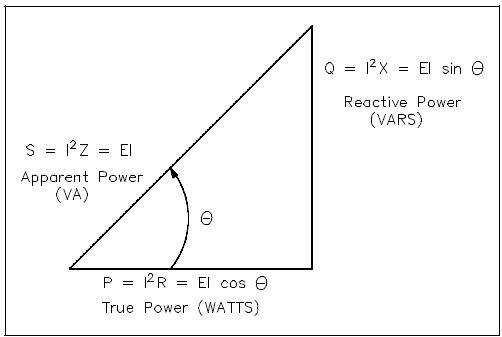
In AC circuits, current and voltage are normally out of phase and, as a result, not all the power produced by the generator can be used to accomplish work. By the same token, power cannot be calculated in AC circuits in the same manner as in DC circuits. The power triangle, shown in Figure 1, equates AC power to DC power by showing the relationship between generator output (apparent power – S) in volt-amperes (VA), usable power (true power – P) in watts, and wasted or stored power (reactive power – Q) in volt-amperes-reactive (VAR). The phase angle (Θ) represents the inefficiency of the AC circuit and corresponds to the total reactive impedance (Z) to the current flow in the circuit.
The power triangle represents comparable values that can be used directly to find the efficiency level of generated power to usable power, which is expressed as the power factor (discussed later). Apparent power, reactive power, and true power can be calculated by using the DC equivalent (RMS value) of the AC voltage and current components along with the power factor.
Apparent Power
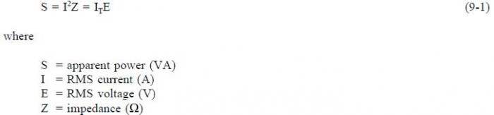
Apparent power (S) is the power delivered to an electrical circuit. Equation (9-1) is a mathematical representation of apparent power. The measurement of apparent power is in volt-amperes (VA).
True Power
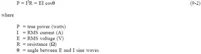
True power (P) is the power consumed by the resistive loads in an electrical circuit. Equation(9-2) is a mathematical representation of true power. The measurement of true power is in watts.
Reactive Power
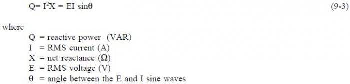
Reactive power (Q) is the power consumed in an AC circuit because of the expansion and collapse of magnetic (inductive) and electrostatic (capacitive) fields. Reactive power is expressed in volt-amperes-reactive (VAR). Equation (9-3) is a mathematical representation for reactive power.
Unlike true power, reactive power is not useful power because it is stored in the circuit itself. This power is stored by inductors, because they expand and collapse their magnetic fields in an attempt to keep current constant, and by capacitors, because they charge and discharge in an attempt to keep voltage constant. Circuit inductance and capacitance consume and give back reactive power. Reactive power is a function of a systems amperage. The power delivered to the inductance is stored in the magnetic field when the field is expanding and returned to the source when the field collapses. The power delivered to the capacitance is stored in the electrostatic field when the capacitor is charging and returned to the source when the capacitor discharges. None of the power delivered to the circuit by the source is consumed. It is all returned to the source. The true power, which is the power consumed, is thus zero. We know that alternating current constantly changes; thus, the cycle of expansion and collapse of the magnetic and electrostatic fields constantly occurs.
Total Power
The total power delivered by the source is the apparent power. Part of this apparent power, called true power, is dissipated by the circuit resistance in the form of heat. The rest of the apparent power is returned to the source by the circuit inductance and capacitance.
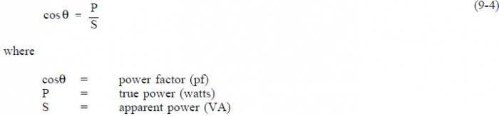
Power Factor
Power factor (pf) is the ratio between true power and apparent power. True power is the power consumed by an AC circuit, and reactive power is the power that is stored in an AC circuit. CosΘ is called the power factor (pf) of an AC circuit. It is the ratio of true power to apparent power, where Θ is the phase angle between the applied voltage and current sine waves and also between P and S on a power triangle (Figure1). Equation (9-4) is a mathematical representation of power factor.
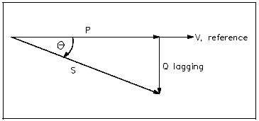
Power factor also determines what part of the apparent power is real power. It can vary from 1, when the phase angle is 0°, to 0,when the phase angle is 90°. In an inductive circuit, the current lags the voltage and is said to have a lagging power factor, as shown in Figure 2.
In a capacitive circuit, the current leads the voltage and is said to have a leading power factor, as shown in Figure 3.
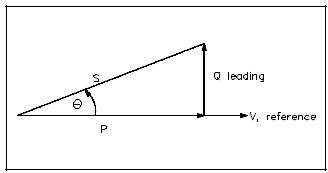
A mnemonic memory device, “ELI the ICE man,” can be used to remember the voltage/current relationship in AC circuits. ELI refers to an inductive circuit (L) where current (I) lags voltage (E). ICE refers to a capacitive circuit (C) where current (I) leads voltage (E).
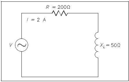
Power in Series R-L Circuit
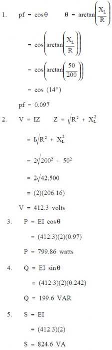
Example: A 200Ω resistor and a 50 ΩXL are placed in series with a voltage source, and the total current flow is 2 amps, as shown in Figure 4.
Find:
- pf
- applied voltage,V
- P
- Q
- S

Solution:
Power in Parallel R-L Circuit
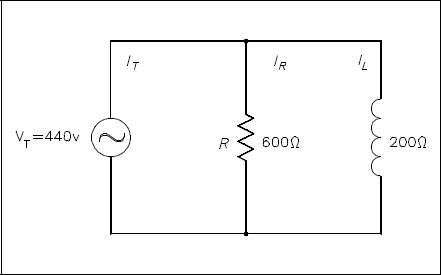
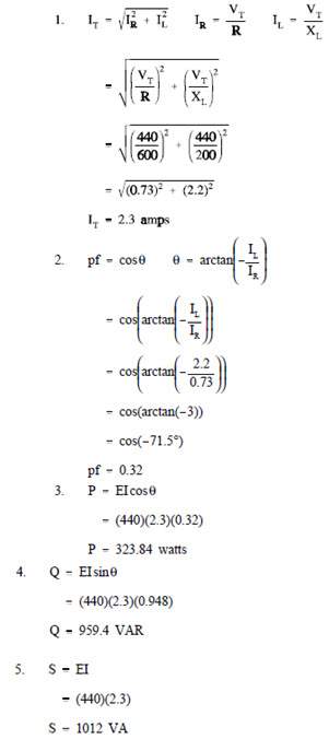
Example: A 600 Ω resistor and 200 Ω XL are in parallel with a 440V source, as shown in Figure 5.
Find:
- IT
- pf
- P
- Q
- S
Solution:
Power in Series R-C Circuit
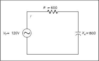
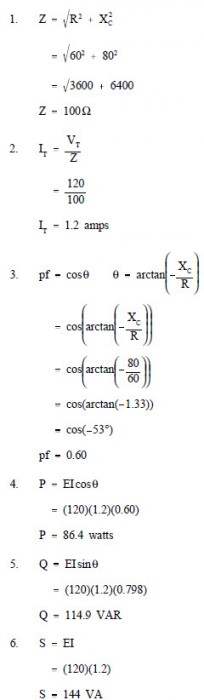
Example: An 80 Ω Xc and a 60 Ω resistance are in series with a 120V source, as shown in Figure 6.
Find:
- Z
- IT
- pf
- P
- Q
- S
Solution:
Power in Parallel R-C Circuit
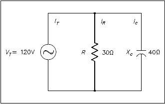
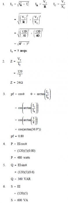
Example: A 30 Ω resistance and a 40 Ω XC are in parallel with a 120V power source, as shown in Figure 7.
Find:
- IT
- Z
- pf
- P
- Q
- S
Solution:
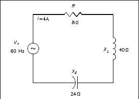
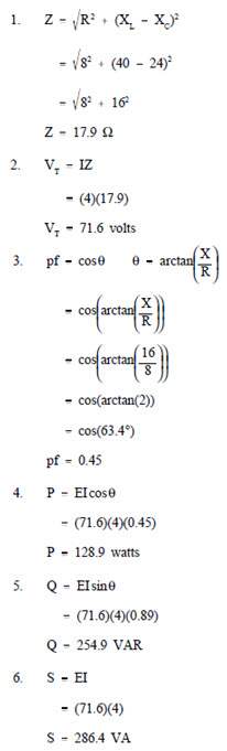
Power in Series R-C-L Circuit
Example: An 8 Ω resistance, a 40 Ω XL, and a 24 Ω XC are in series with a 60 Hz source with a current flow of 4 amps, as shown in Figure 8.
Find:
- Z
- VT
- pf
- P
- Q
- S
Power in Parallel R-C-L Circuits
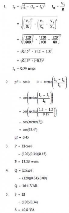
Example: An 800 Ω resistance, 100 Ω XL, and an 80 Ω XC are in parallel with a 120V, 60Hz source, as shown in Figure 9.
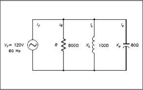
Solution:
Three-Phase Circuits
The design of three-phase AC circuits lends itself to a more efficient method of producing and utilizing an AC voltage.
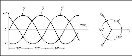
Three-Phase Systems
A three-phase (3φ) system is a combination of three single-phase systems. In a 3φ balanced system, power comes from a 3φ AC generator that produces three separate and equal voltages, each of which is 120° out of phase with the other voltages (Figure 10).
Three-phase equipment (motors, transformers, etc.) weighs less than single-phase equipment of the same power rating. They have a wide range of voltages and can be used for single-phase loads. Three-phase equipment is smaller in size, weighs less, and is more efficient than single-phase equipment.
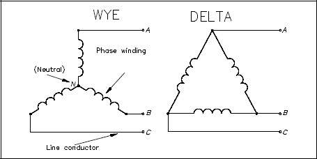
Three-phase systems can be connected in two different ways. If the three common ends of each phase are connected at a common point and the other three ends are connected to a 3φ line, it is called a wye, or Y-, connection (Figure 11). If the three phases are connected in series to form a closed loop, it is called a delta, or Δ-, connection.
Power in Balanced 3φ Loads
Balanced loads, in a 3φ system, have identical impedance in each secondary winding (Figure 12). The impedance of each winding in a delta load is shown as ZΔ(Figure 12a), and the impedence in a wye load is shown as Zy (Figure 12b). For either the delta or wye connection, the lines A, B, and C supply a 3φ system of voltages.
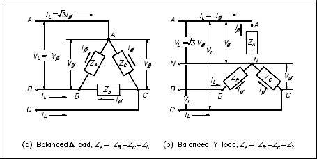
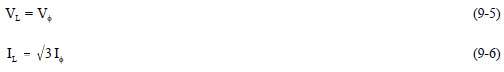
In a balanced delta load, the line voltage (VL) is equal to the phase voltage (Vφ), and the line current (IL) is equal to the square root of three times the phase current (3φI). Equation (9-5) is a mathematical representation of VL in a balanced delta load. Equation (9-6) is a mathematical representation of IIL in a balanced delta load.
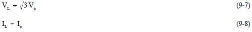
In a balanced wye load, the line voltage (VL) is equal to the square root of three times phase voltage (φ), and line current (IL3V) is equal to the phase current (Iφ). Equation (9-7) is a mathematical representation of VL in a balanced wye load. Equation (9-8) is a mathematical representation of IL in a balanced wye load.
Because the impedance of each phase of a balanced delta or wye load has equal current, phase power is one third of the total power. Equation (9-10) is the mathematical representation for phase power (Pφ) in a balanced delta or wye load.

Total power (PT) is equal to three times the single-phase power. Equation (9-11) is the mathematical representation for total power in a balanced delta or wye load.
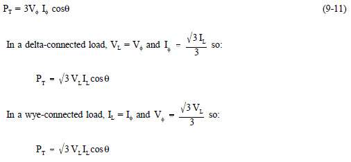
As you can see, the total power formulas for delta- and wye-connected loads are identical.
Total apparent power (ST) in volt-amperes and total reactive power (QT) in volt-amperes-reactive are related to total real power (PT) in watts(Figure 13).
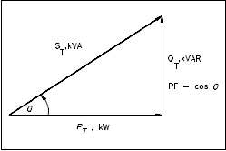
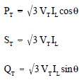
A balanced three-phase load has the real, apparent, and reactive powers given by:
Example 1:
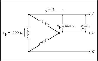
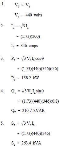
Each phase of a delta- connected 3φAC generator supplies a full load current of 200 A at 440 volts with a 0.6 lagging power factor, as shown in Figure 14.
Find:
- VL
- IL
- PT
- QT
- ST
Solution:
Example 2:
Each phase of a wye- connected 3φ AC generator supplies a 100 A current at a phase voltage of 240V and a power factor of 0.9 lagging, as shown in Figure 15.
Find:
- VL
- PT
- QT
- ST
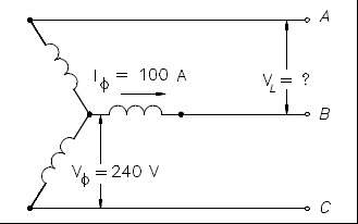
Solution:
Unbalanced 3φ Loads
An important property of a three-phase balanced system is that the phasor sum of the three line or phase voltages is zero, and the phasor sum of the three line or phase currents is zero. When the three load impedances are not equal to one another, the phasor sums and the neutral current (In) are not zero, and the load is, therefore, unbalanced. The imbalance occurs when an open or short circuit appears at the load.
If a three-phase system has an unbalanced load and an unbalanced power source, the methods of fixing the system are complex. Therefore, we will only consider an unbalanced load with a balanced power source.
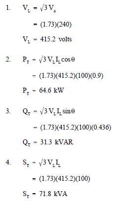
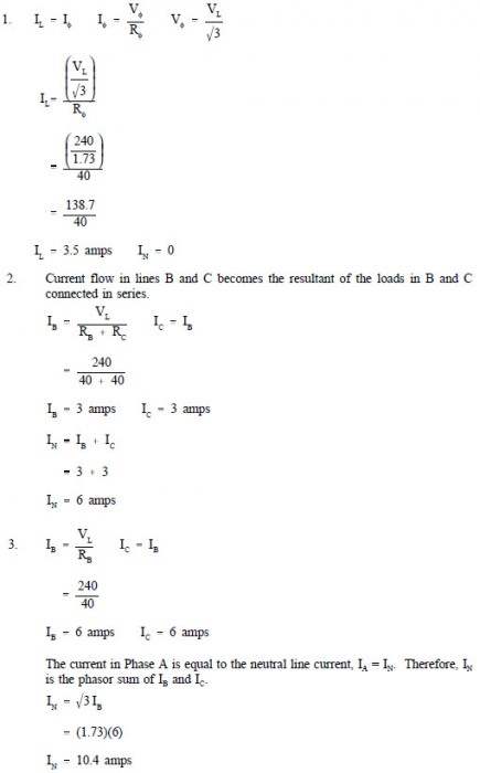
Example: A 3φ balanced system, as shown in Figure 16a, contains a wye load. The line-to- line voltage is 240V, and the resistance is 40Ω in each branch.
Find line current and neutral current for the following load conditions.
- balanced load
- open circuit phase A (Figure 16b)
- short circuit in phase A (Figure 16c)
In a fault condition, the neutral connection in a wye-connected load will carry more current than the phase under a balanced load. Unbalanced three-phase circuits are indicated by abnormally high currents in one or more of the phases. This may cause damage to equipment if the imbalance is allowed to continue.